Project: Flexible Wood

Click to see gallery of full-sized images…
Introduction
The engineering classes in my high school were divided in 5 levels, and students had to have at least completed the first one in order to use the laser-cutter we had. When I started this class, my engineering teacher showcased some of his previous students’ projects, one of which particularly caught my attention: making a sheet of wood flexible. The simplicity of such a feat was fascinating to me, as all that needed to be done was simply laser-cutting a space-filling design onto it. Thus, exploring different flexible wood designs became one of the primary projects I worked on in that class.
Design Process
I first began with some example cuts that we had, using some of the following designs:


As seen in the gifs, I discovered that the way the wood is cut will affect its range of movement. For example, the fifth design above could bend all the way back to the board while the eighth couldn’t bend at all. Additionally, some of these designs did more than just make the wood flexible: with designs 4-7, the board is able to be stretched and compressed a little. Inspired by these designs, I set out to make designs of my own that could bend in all directions, which are shown below:


I expected that the curvy designs would bend easier than their sharp-end counterparts, as well as the final 3 designs would have a better range of flexibility than the first two. However, they all seemed to bend on a similar level, with the final circular design actually being the most difficult to maneuver. In addition, given that these designs were not as flexible as the fifth example design above, I realized that line cutting thickness directly affects the boards flexibility: the greater the width, the more it can bend.
Using Space-Filling Curves
After being introduced to L-Systems through my PlotEquation plugin, I realized that many of these curves resemble the Hilbert Curve and proceeded to create flexible wood using that design. Unfortunately, it did not work as I had intended, given that the empty space in the Hilbert Curve is not a single path":

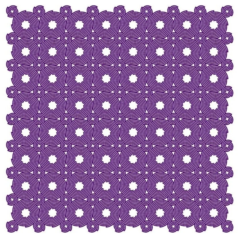
This was a little discouraging at first, until it hit me that I could simply “invert” the curve so that the lines and empty space switch. This produced much nicer results, as shown in the following gif:

Given that the Hilbert curve is a single path, the results of this tests worked quite nicely. This means that any space-filling single-curve can be used to design flexible wood. The following gifs show designs using the Hilbert II Curve and Moore Curve, respectively:


Extension into 3D
While it might seem impossible to extend this idea into 3D given that the sheets of wood are flat, 3D-printing provides an appealing alternative. Using 3D Hilbert Curves, the following two objects were printed:

Note that they are complements to one another: one is the curve itself, while the other is a box with the curve cut out from its interior. The curve was capable of being easily manipulated while the other was strictly rigid, as shown in the following gifs:

