Project: Dual Image Objects

Introduction
One of the units in my high school engineering class was modeling “dual image” objects, where 2 different images will appear depending on how it’s rotated. The process for designing such objects is straightforward: extrude one of the 2D-curves (that represents the first image you want) along the X-axis and the other (the second image) along the Y-axis, then trim the excess material. This process can be optimized by using the curves to wirecut a box. Both methods are shown below to see what’s visually happening.

Front view: wolf

Side view: lion? eagle? (I forgot what this was)
Design Process
Note that, with both methods, the smaller curve will limit how much the detail other has. As such, in order to fully show both images, both the curves will need to positioned and scaled in such a way that their minimum and maximum extents on the vertical axis match each other. The curves used are shown below:

Curve 1

Curve 2
Extrusion Method
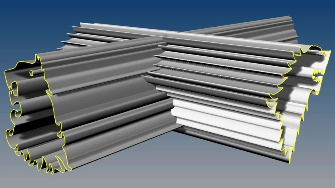
Extruded Curves

First Trim

Second Trim

Third Trim

Fourth Trim
Box Method

The Box

Wirecut 1

Wirecut 2
Method Comparison

The Box method produces a more detailed object than the Extrusion method, which would have required more trimming to get the same level of detail